- Thermocouples
- Screw-in thermocouple
- Plug-in thermocouple
- Dipstick-Thermocouples
- Wire thermocouple
- Sheathing-tube thermocouples
- Sheathed thermocouple
- Surface thermocouple
- Screw-in resistance thermometer
- Plug-in resistance thermometer
- Wire resistance thermometer
- Sheating tube resistance thermometer
- Sheathing resistance thermometer
- Accessories Thermocouples
- Surface resistance thermometer
- Sheathed thermocouple with terminal head
- Thermo connectors
- More products
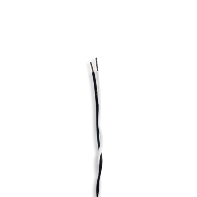
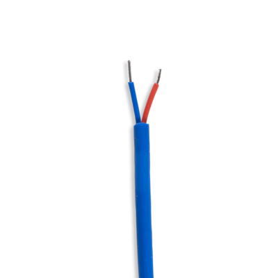
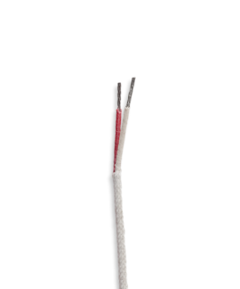
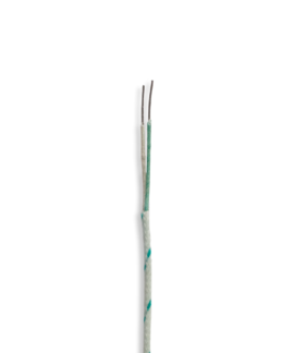
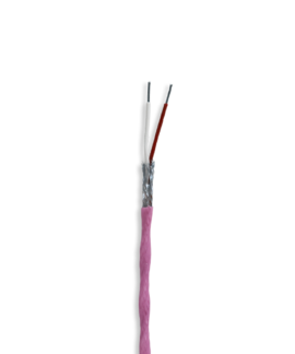
Thermowires and compensating wires
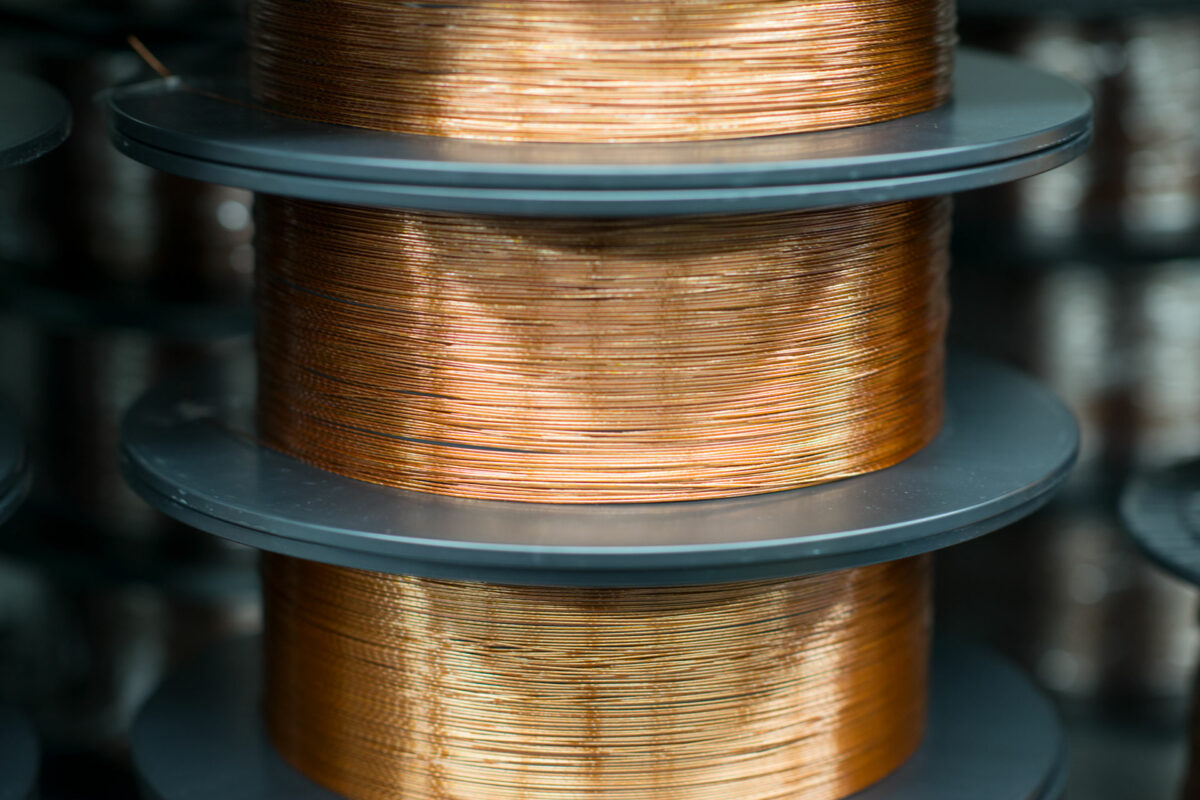
In most cases, the measuring device cannot be operated in the immediate vicinity of the measuring point since this is situated inside machinery or in similar hot, dirty environments. The measuring signal needs to therefore be transferred over a certain distance. Thermowires (extension cables) or compensating wires can be used for this.
The wires in a thermowire are made from the same material as the wires in the thermocouple. The thermal voltage therefore appears only when it is connected to the device, and is not distorted. With compensating wires, on the other hand, materials are used that are similar to those of the thermocouple. Thermowires are supplied as standard with a limit deviation in tolerance class 1. Compensating wires, however, are only available in tolerance class 2. We only use thermowires from tolerance class 1. The limit value deviations only apply for the temperature range specified under the usage temperature (DIN EN 60584-3). The usage temperature relates to the temperature of the wire, while different limit deviations apply to connected thermocouples. A thermowire or compensating wire cannot be connected to a thermocouple of a different type.
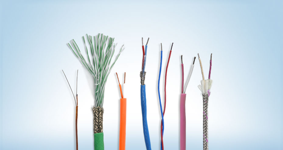
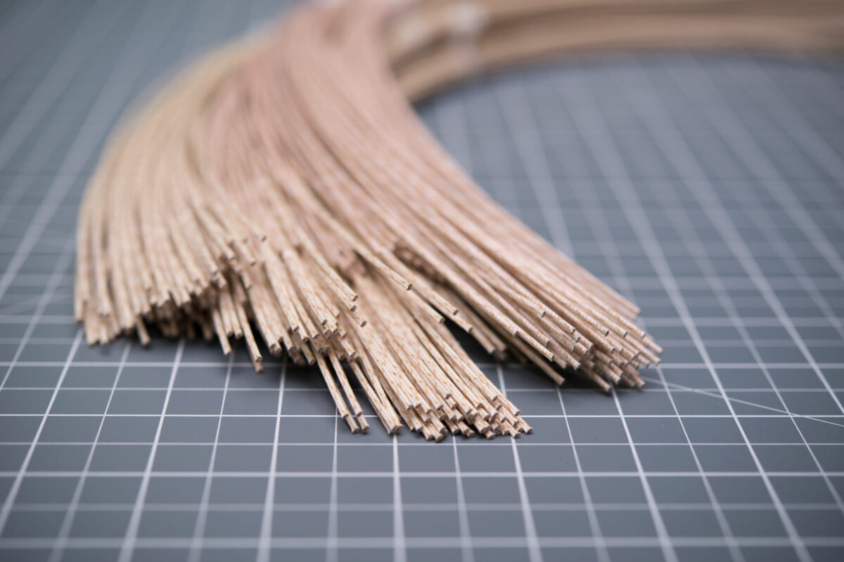
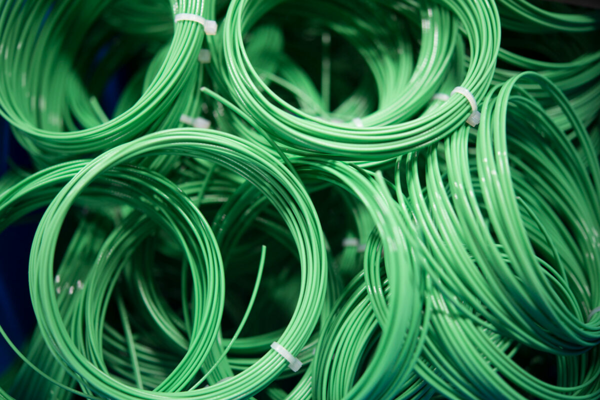
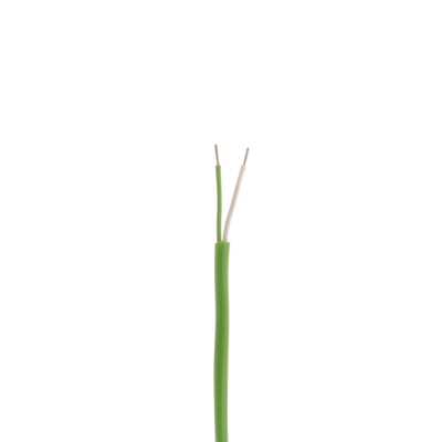
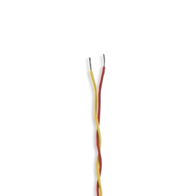
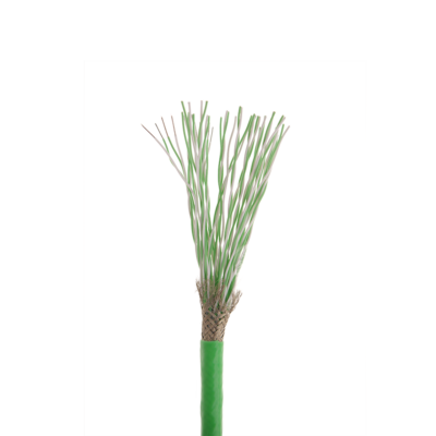
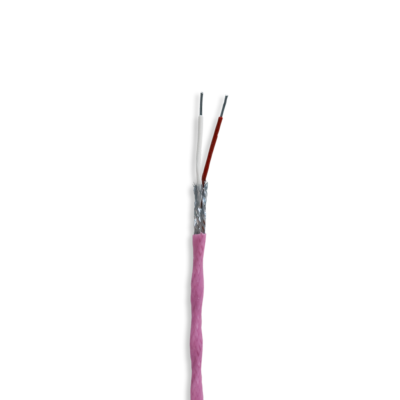
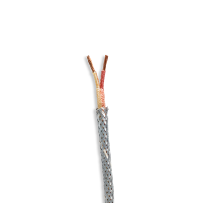
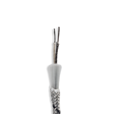
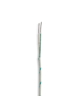
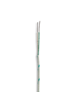
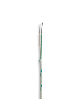
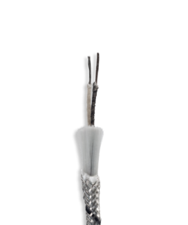
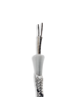
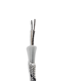
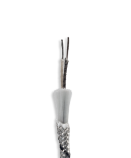
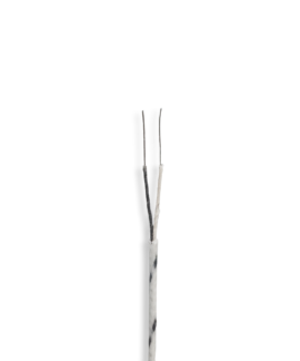
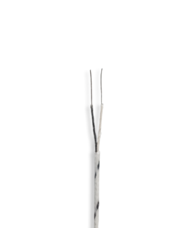
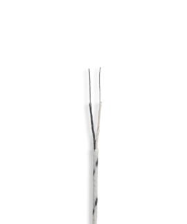
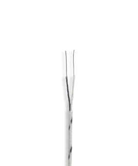
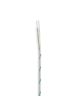
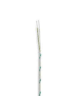
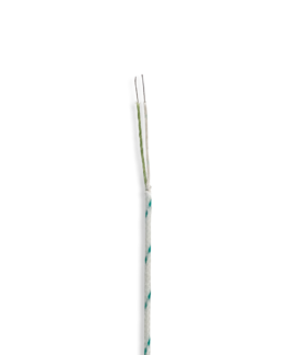
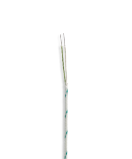
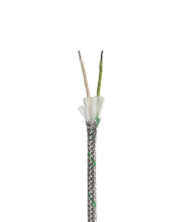
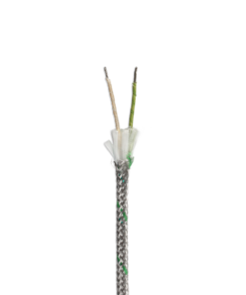
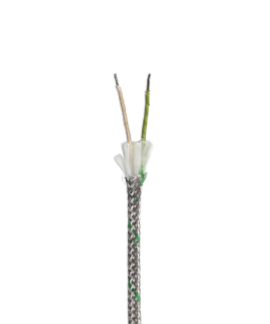
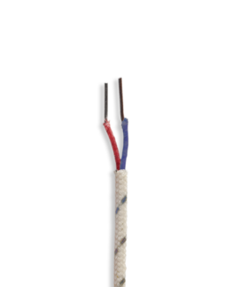
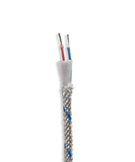
Images of thermowires and compensating wires
Insulation
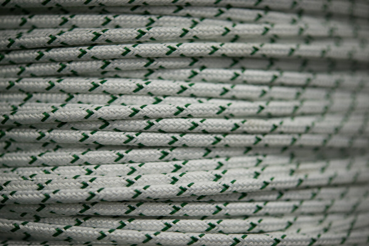
Thermowires are primarily insulated with Kapton, fibreglass, Teflon or silicone. A copper mesh is integrated with some wires in order to shield the wires from electromagnetic interference.
Where wires are exposed to particularly intensive mechanical stress, they should be protected with a stainless steel sheath. A stainless steel sheath can be combined with all types of insulation material.
PVC or silicone is frequently used to insulate compensating wires since their usage temperatures match those of the compensating wire.
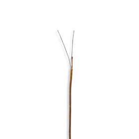
(Polyimide) is chemically very resistant, has good insulating properties and is heat-resistant to +285 °C. Even with a small diameter of the Kapton, good electrical insulation properties can be achieved.
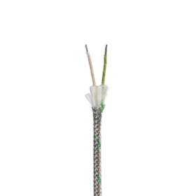
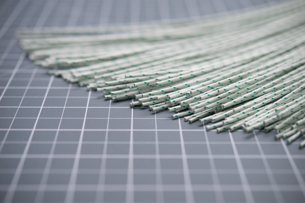
Fibreglass is laid or woven as a fabric around the wires and sealed with resin. Fibreglass-insulated wires have a heat resistance of up to +1,100 °C. For applications under mechanical strain, further wrapping of the fibreglass-insulated wire with a VA mesh is recommended.
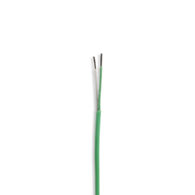
Teflon is chemically resistant to acids, bases, alcohols, petrols and oils. It is flexible and slides very easily thanks to its low friction coefficient. It is also difficult to adhere to anything, since there are scarcely any materials that stick to Teflon. The usage temperature ranges, depending on the type of Teflon used, from -190 °C to +260 °C. For wire insulation, we use FEP Teflon (-100 °C to +205 °C), PTFE Teflon (-190 °C to +260 °C) or PFA Teflon (-190 °C to +260 °C).
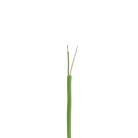
Silicone is highly flexible and does not become brittle even at low temperatures. Its usage temperature is from -50 °C to +180 °C.
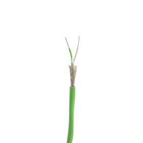
PVC is a commonly used insulating material in the electrical engineering sector. Its usage temperature is from -20 °C to +90 °C.
Properties of insulation materials
| Material | Usage temperature constant (°C) Approx. 25,000 h |
Usage temperature temporary (°C) (hours) |
Dielectric strength kV/mm (20 °C) |
General chemical resistance |
|---|---|---|---|---|
| PVC | –20 to +90 | +120 | 25 | Limited |
| FEP | –100 to +205 | +230 | 25 | Very good |
| PTFE | –190 to +260 | +300 | 20 | Very good |
| PFA | –190 to +260 | +280 | 25 | Very good |
| Kapton | –190 to +220 | +400 | 287 | Very good |
| Silicone | –50 to +180 | +250 | 30 | Limited |
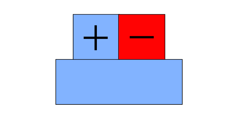
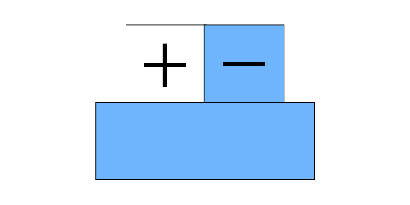
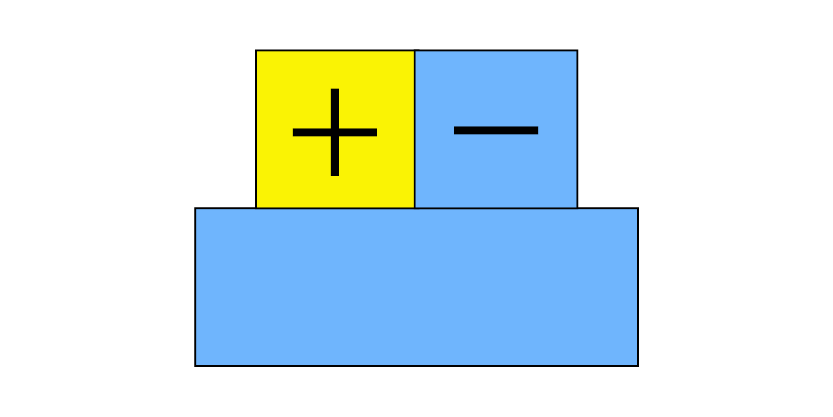
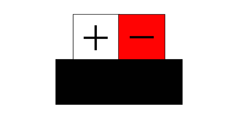
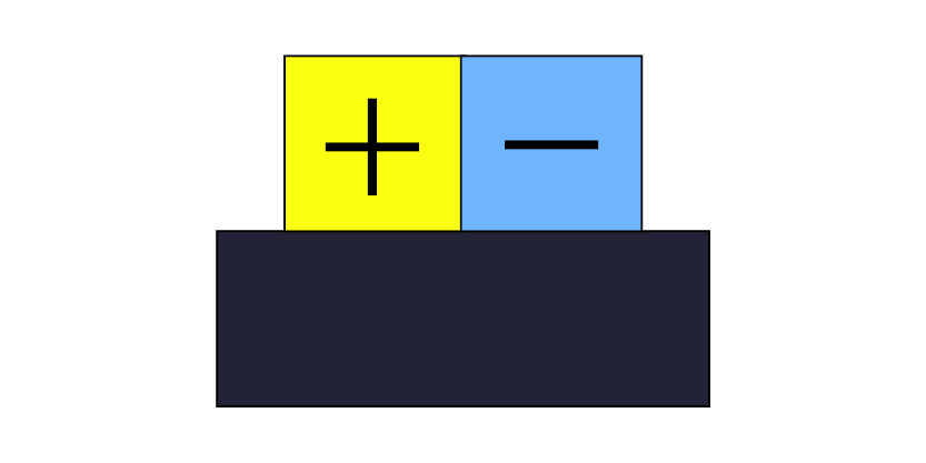
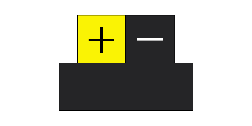
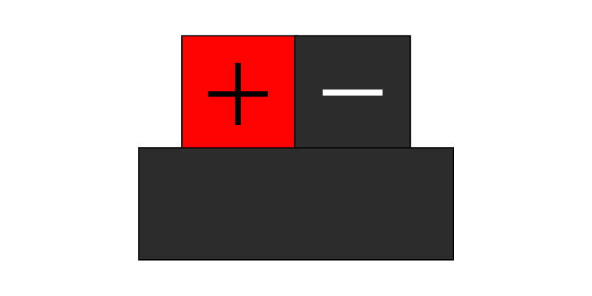
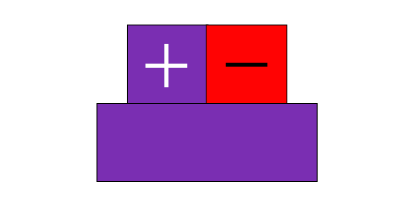
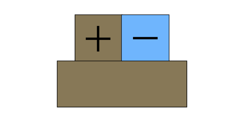
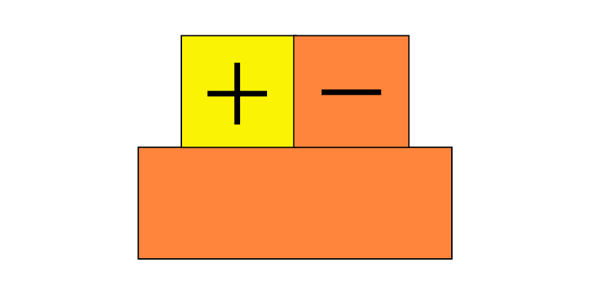
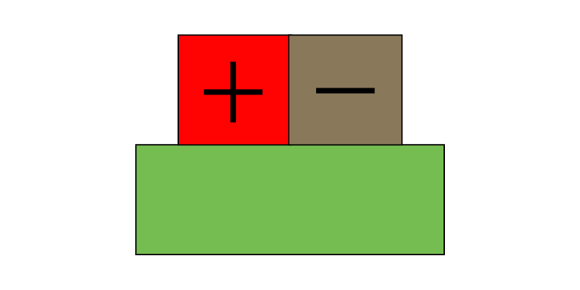
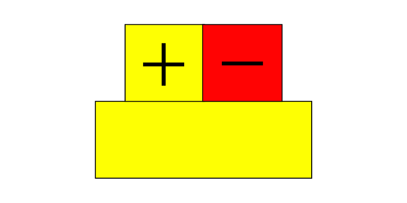
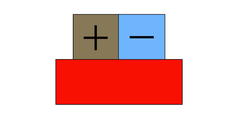
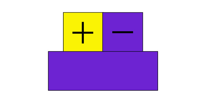
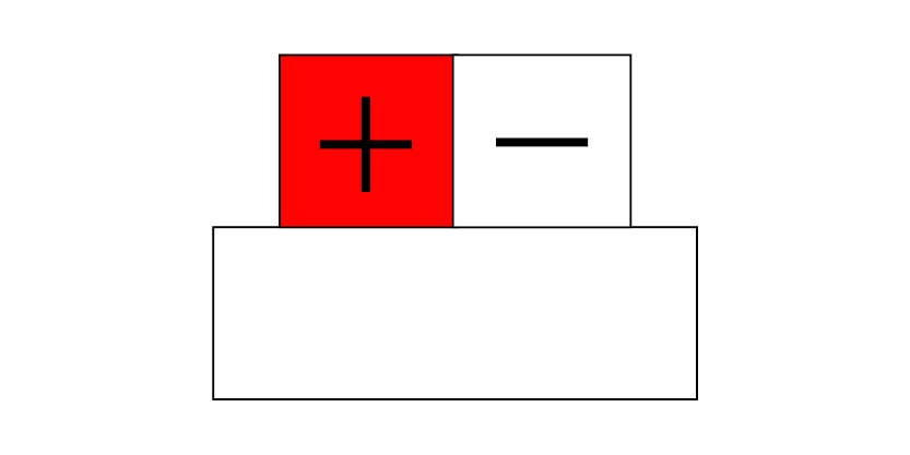
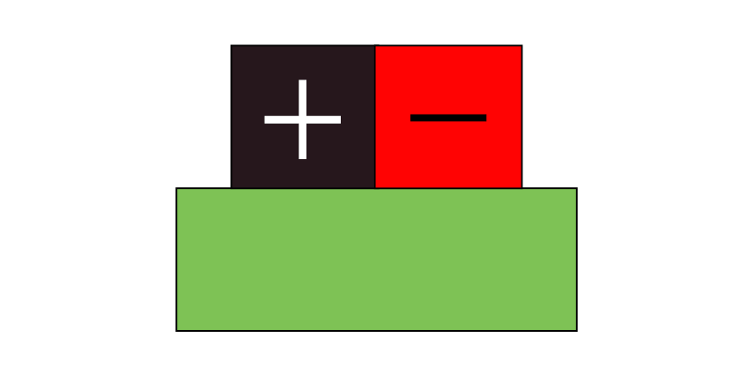
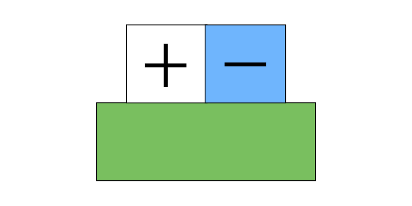
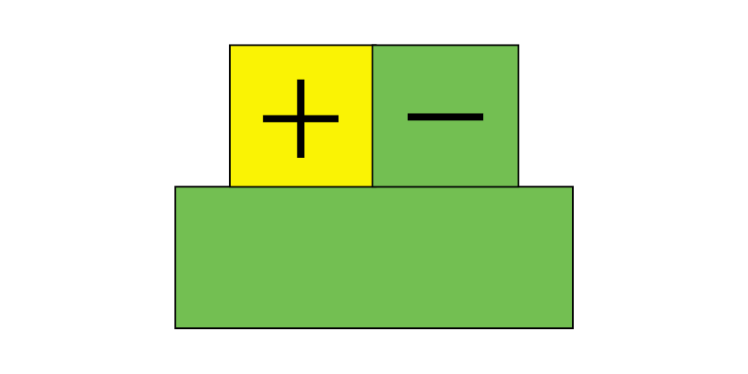
Colour identifications for thermowires and compensating wires
| Country | |||||||
|---|---|---|---|---|---|---|---|
| Type | Material | IEC 60584-3 | DIN 43714 | ANSI MC 96.1 | BS 1843 | NF C 42-324 | |
| – | + | ||||||
| T | Cu | CuNi | 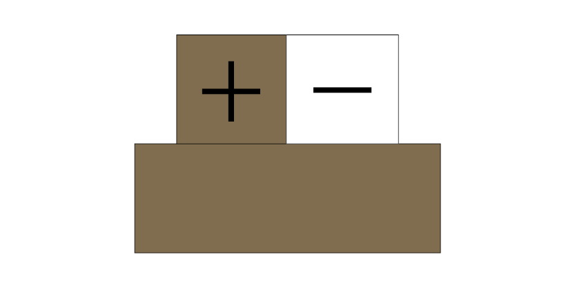 |
 |
 |
 |
|
| U | Cu | CuNi | 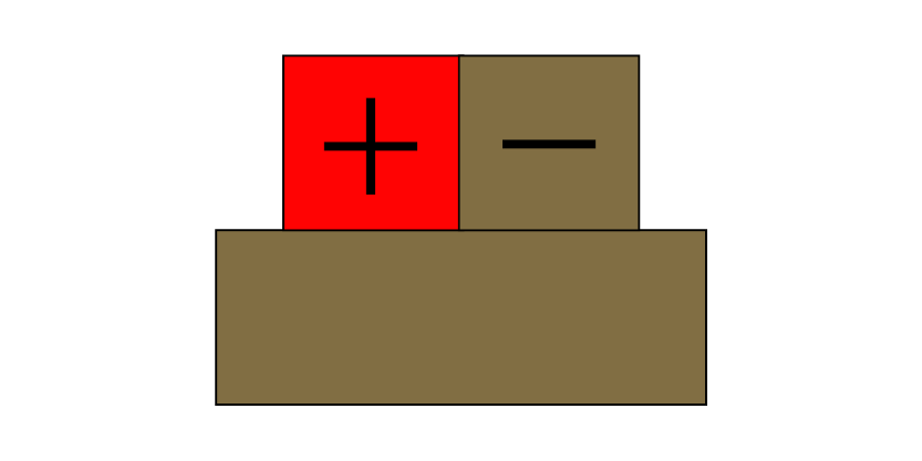 |
||||
| J | Fe | CuNi | 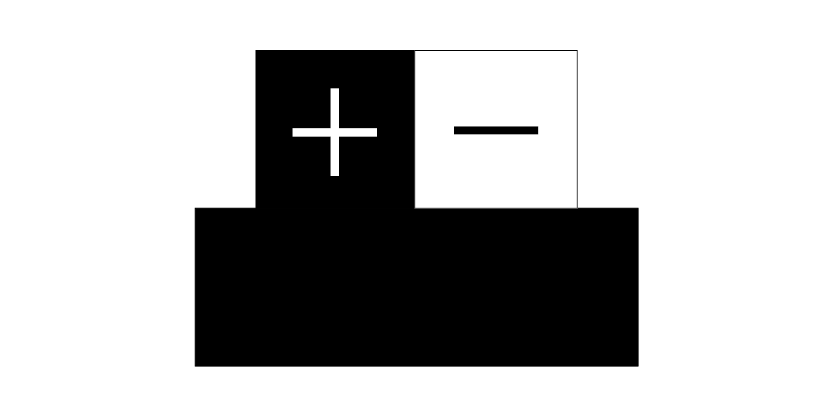 |
 |
 |
 |
|
| L | Fe | CuNi | 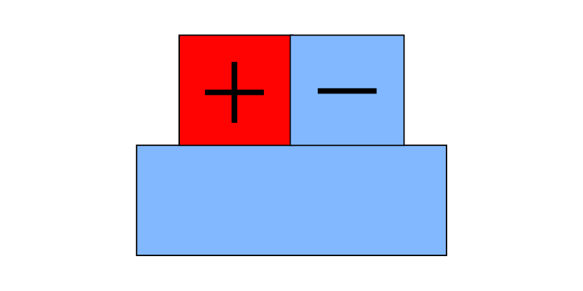 |
||||
| E | NiCr | CuNi | 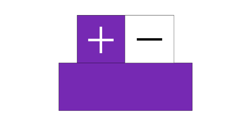 |
 |
 |
 |
 |
| K | NiCr | Ni | 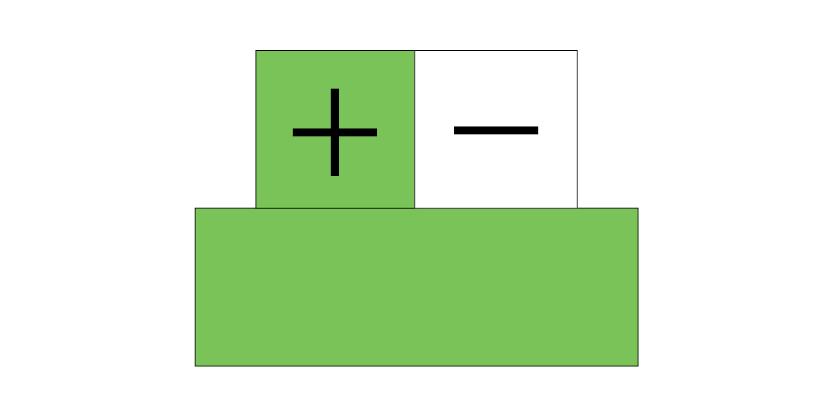 |
 |
 |
 |
 |
| N | NiCrSi | Ni | 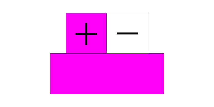 |
||||
| R | PtRh13 | Pt | 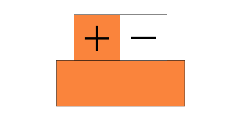 |
 |
 |
 |
 |
| S | PtRh10 | Pt | |||||
| B | PtRh30 | Pt6Rh |  |
 |
 |
 |
|
12,60 €
31,50 €
63,00 €
126,00 €
22,00 €
55,00 €
110,00 €
220,00 €
11,00 €
27,50 €
55,00 €
110,00 €
11,00 €
27,50 €
55,00 €
110,00 €
23,80 €
59,50 €
119,00 €
238,00 €
